
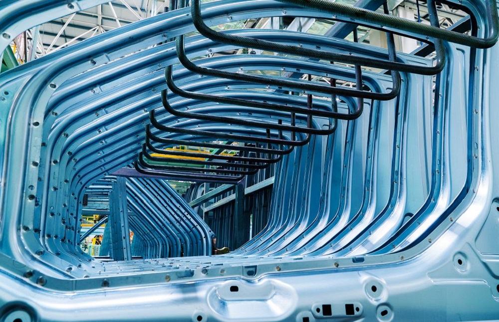
Be aware that moving, enlarging, or adding a simple hole involves a lot of interfaces; even a single hole change can sideline both the manufacturing line and the full vehicle build if not managed well. gyn9038/Getty Images/iStockphoto
While designing and engineering automotive body structures for manufacturing, you may receive some of these requests on a regular basis:
“Can you just move this hole about 5 mm?”
“I just need to shift this side wall 3 mm inboard.”
“We just need to change the size of this hole.”
“Can you just cut off 1 mm from this flange?”
These are common requests for a body-in-white (BIW) structures engineer—before, during, and after a vehicle launch. And that’s OK; this is normal. It’s important to remember that the BIW structure is a support system, and its main function is to support other vehicle systems. But be aware that moving, enlarging, or adding a simple hole involves a lot of interfaces, such as:
- Die tooling set (tandem, transfer, or progressive).
- Dies, punches, blank holders, binders, gas springs, bolts.
- Control gauges, welding fixtures, clamps, grippers.
- Sourcing, timing, logistic flow, part number tracking.
Keep in mind that even a simple hole change requires that you check through the entire production chain to prevent problems. Even a single hole change can stop the manufacturing line and the full vehicle build if not managed well.
There is no easy or simple BIW change. Each request needs close attention, no matter the product stage, so always keep your eyes open—especially when you get a call to change the design within the word “just.”
Interfaces
Interfaces are important in the design and manufacture of a vehicle system—even more so for BIW structures. Most of the time interfaces determine the final decision about the design strategy and, at times, the body architecture.
But what exactly does interface mean? Simply put, it is every single part and all the vehicle content near your entire part. It doesn’t matter if your part is touching another part directly or with a certain clearance, everything counts—including all manufacturing processes and required tools.

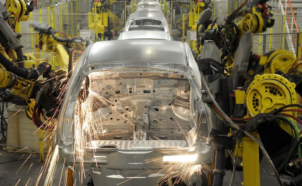
Keep in mind that your part is never isolated, even if you are designing a single part. Other systems and processes, such as welding, are affected by the part changes. RicAguiar/E+/Getty Images Plus.
Scary, right? Yes, it is. A good analogy might be to think of your refrigerator. Every shelf has its own space, volume, and package limit. All the stuff inside of the refrigerator are the parts.
One thing is clear to everyone working in automotive: Many parts and dozens of steps are needed to complete a single unit. That is when all system interfaces take place. Have you ever tried to put something inside the refrigerator but no space was available?
To properly manage this complex workload, we basically split the system interface by two main analyses: the design system and the manufacturing process.
Design System. Check all part-to-part interfaces, considering the dynamic and static clearances, including system function and related engineering deliverables.
Manufacturing Process. Consider all production steps, including the tools for bolting, welding, loading, installation, and ergonomics, plus production constraints around painting, the body shop, and final assembly.
A good example of a system interface is the front fender. You need to manage how its design interfaces with the front doors, hood, body side, front structures, head lamps, fascia, arch liner, and tire envelope. You also need to consider the manufacturing process for handling, loading, and bolting the parts, including power tool access.
Always keep in mind that your part is never isolated, even if you are designing a single part. Other systems and processes are affected by the part.
Engineering Changes Require Validation
There is one constant for all OEMs—ongoing design changes. There may be different reasons for them, but at some point during the vehicle life cycle, part changes will be required.
Another constant is that the production line cannot stop. Well, the line can stop, but it should never stop during the time planned for mass production, which equates to salable units.
Everything needs to be given the utmost attention and should be well synchronized. All stakeholders should ensure the part replacement won’t affect product quality negatively or disrupt the manufacturing line schedule.
Whether a product change involves raw material or a gauge, change is change. You need to treat the altered part as new to the current production chain. To ensure part quality and fit, you need to run some validations before proceeding to replace parts permanently at the production line. Morsa Images/E+/Getty Images.
Whether a product change involves raw material or a gauge, change is change. You need to treat the altered part as new to the current production chain until you are highly confident that you can replace the current parts with the new ones.
The main reasons for design changes are:
- To create parts commonality among new models.
- For cost reduction or design efficiency.
- To achieve process and product improvements.
- To correct a design (yes, sh** happens).
To ensure part quality and fit, you need to run some validations before proceeding to replace parts permanently at the production line. For example, before replacing a part’s material grade or gauge permanently, you must first follow a few validation steps:
- Perform initial stamping validation on 10 parts.
- Test 30 parts for stamping and system functions.
- Validate the system and vehicle on 150 parts.
The pain point is running all those validations without disrupting the current production (facility and supplier). You still need to run some vehicle testing to ensure the part quality and attribute deliverables.
Only after you successfully complete these tryouts and system validations can you proceed to implement the changes at the shop floor and production lines permanently. It’s important to note that production validation depends on the severity of the change, part complexity, and system function.
Only one thing is standard: “Just” is never the case.
What Is a Design Trigger?
A design trigger is a simple strategy to manage the body structures loads. A trigger’s main function is to drive body system behavior and support the entire vehicle’s structure. It should help manage and absorb the load inputs—kind of like fuses.
A good example of a design trigger occurs in the front bumper beam assembly, which is quite a complex system to develop. The bumper assembly must be strong enough to receive the frontal impact but also be able to absorb and manage the load paths into oncoming vehicle structures. Therefore, some parts in a front bumper beam assembly are designed to be weak and to be crushed. Sometimes weakening some areas improves the overall structure’s performance. The triggers have important functions on this workload. It may seem counterintuitive, but increasing a part’s strength does not always improve vehicle performance. The body system has to be balanced and developed to manage all load inputs.
The bumper beam assembly impact behavior may affect the A-Pillar performance. That’s why you need to manage this path after the first input at the bumper beam.
Designing triggers involves very complex and sensitive engineering tradeoffs. Triggers are key features to support this achievement, but just adding triggers doesn’t mean you can manage the loads easily and deliver the expected results. You have to consider other inputs until the target is achieved—the triggers are only one.
BIW Structures Engineers Should Know the Stamping Process
It is necessary for BIW structures engineers to understand the stamping process. While you don’t necessarily need to be a stamping expert (though, it would be helpful if you were) it really is only necessary to have some knowledge about the sheet metal forming process and methods, specifically manufacturing constraints. Before you drive and lead a sheet metal part design, you have to, at the very least, understand how a part is made.
In addition, you’ll face problems during the development phase that demand major design changes. As a result, you’ll need to be able to analyze and provide feasible solutions.
For example, do you know what springback is? Do you know how to control and counter it with design or metal manufacturing processes? This is only one constraint that you’ll likely encounter when designing a sheet metal part. You need to be able to solve it with or without support from stamping colleagues and toolmakers.
What are the main differences between progressive, tandem, and transfer die processes; stamping and roll forming; and cold and hot forming? You need to know these terms and how these processes affect the design.
Bear in mind that a nice, colored CAD model on your computer screen is just the beginning. The part has to be manufactured, and all steps related to process and manufacturing are also part of the product design. The product engineering workstream ends up only at the shop floor. The stamping process also affects your part costs and quality and drives the product design. You need to understand how to provide a proper solution and deliver a feasible design on the first sketch.
Avoid Overengineering
Last but not least, always ask yourself: “Do I really need to add these features into the design?”
Asking yourself this simple question at the right time can save money and time. It isn’t rare for sheet metal parts to have oversized designs with beads, pockets, flanges, and even holes added that have no real purpose.
It’s an understandable and normal mistake to make when designing new parts using an existing design as a reference. If someone added these features before, let’s keep them in, right? Wrong.
It’s not that you won’t need to add many of the same features into your new design, but you do need to understand the technical reasons as to why before adding any features into your new design. Just because someone used a feature before doesn’t mean you’ll need it too. You’re probably wondering, “How will I know?”
You can redesign sheet metal parts and remove features from a previous design while keeping the same system performance, delivering a cleaner, cheaper design. Yes, it’s possible, and you don’t have to be Harry Potter to do it.
Beads. The most overused feature in part design are the beads across bending lines. Designers and engineers often use these beads for springback control and to stabilize and stiffen the side walls. However, beads are only needed in situations when the system really requires it and where stamping simulations indicate springback with no other option to control it. Beads are not required in every single bending line. Even a few beads across the bending line might increase the tooling and part costs. If you’re unsure, imagine designing the blank holder and dies interface with and without beads.
The point is, adding features into a stamped part design often increases the part and tooling costs. Simply put, the more features, the more complex die sets will be, and the longer it will take to manufacture.
Material Gauge. Another common overdesign is material thickness. Using overly thick material is like a hunter unsure if they’ll encounter a little bird or a big lion while crossing the jungle, so they carry an elephant gun to protect themselves from a T-Rex.
The thinner the sheet, the cheaper the tools and the less stamping force needed. This includes gas springs, springs, punches, and dies.
A good rule of thumb is to always start a new design as clean, simple, and flat as possible. The right time for adding features is after starting the stamping simulations, attributes, and function analysis—never before! A clean and simple design doesn’t reduce a part’s functionality because they are designed to deliver functions. If no technical reasons exist to add a feature, don’t do it.
This is the main difference between knowledge and experience. Not only is it important to know the design techniques, you have to know how and when to apply them.
Body structures engineering is fast, fascinating, and q
uite dynamic, so keep learning on a daily basis and do your best to share your experiences and findings with your team. That is a good way to learn and grow your skills.


